Control of the steel ropes of hoists: frequency, type of damage and replacement
Donati Sollevamenti S.r.l. supplies consultancy and assistance for the control and maintenance of steel ropes for hoists
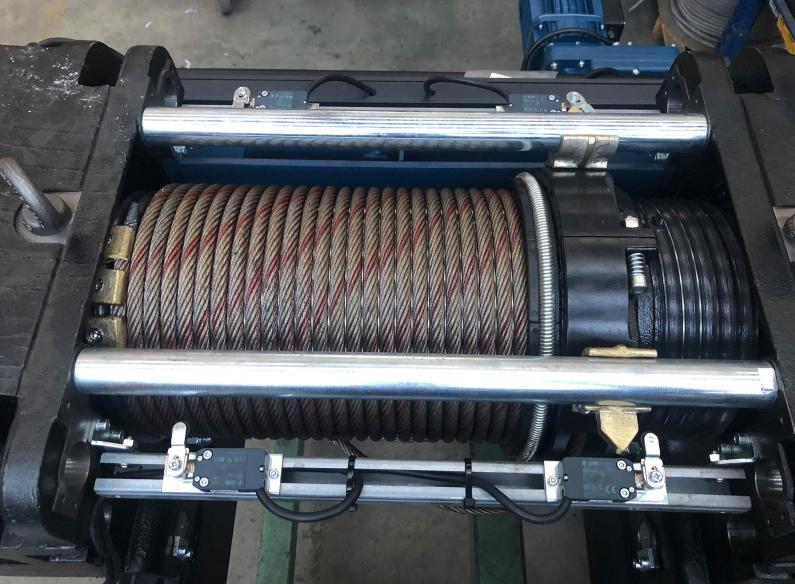
Controlling the metal cables used in hoists and in other load lifting systems reduces the risk of accidents and extends the life of this accessory. Here we will explain the characteristics of a metal rope or cable used to lift loads, how often inspections should be carried out, the signs of damage and wear that personnel should look for and when parts should be replaced.
The elements of a steel rope
Steel ropes have three main parts:
- The wires, these are the basic component of the rope. They are made of steel, possibly galvanised to protect them from atmospheric agents and corrosion. The most important characteristic of a wire is, naturally, its resistance, expressed in Newton per mm2 (N/mm2). Carbon steel wires have five resistance classes:
- 1370 N/mm2
- 1570 N/mm2
- 1770 N/mm2
- 1960 N/mm2
- 2160 N/mm2
- The strands, comprising a number of wires laid helically around a core:
- The core, the centre of the rope around which the strands are wound. The core can be a strand or a rope. Its function is to support the strands, to act as a container and vehicle for the lubricant and to provide from 10 to 50% of the resistance of the entire rope.
Characteristics of the ropes
The characteristics of a rope:
- The diameter, calculated by measuring the circumscribed circle of the cross-section of a section of straight rope;
- The formation and number of wires, values that the technical data sheets show in the following order: the number of strands, the number of wires in each strand and the composition of the core;
- The lay of the wires and strands, that can be either:
- Right hand lay when it starts from bottom left and reaches top right, indicated on the technical data sheets with the letter Z;
- Left hand lay when it starts from bottom right and reaches top left, indicated on the technical data sheets with the letter S.
- The lay of the ropes, dictated by the combination of the lay of the wires in the strands and the strands in the rope. In this respect there are two options:
- Cross lay, also called ordinary or regular. This is the most common type of rope with the wires in the strands lying in the opposite direction to that of the strands in the rope;
- Parallel lay, also called Lang. In this type of rope the wires and strands are all laid in the same direction.
- Rope with right cross lay sZ
- Rope with left cross lay zS
- Rope with right parallel lay zZ
- Rope with left parallel lay sS
- The metal section, that represents the sum in mm2 of the straight transversal sections of all the wires of the rope;
- The breaking load, described by three values:
- The minimum breaking load, used for accident-prevention regulation purposes;
- The effective load, obtained in stress-rupture tests. This value must always be greater than the minimum one;
- The additional load, a purely theoretical value obtained by summing the breaking loads of the individual wires;
- The unitary weight, calculated based on the weight of the rope. This is an approximate value that in practice can vary from -3% to +5%.
The ropes, like other lifting accessories, such as belts or chains, must by marked and accompanied by a plate, label or irremovable ring. The plate, label or ring must bear CE marking, identification details of the manufacturer or its representative and the following information:
- Diameter;
- Length;
- Material of the product;
- Any special metallurgical treatments to the material;
- The maximum tolerable load during use.
Frequency of rope inspections
Based on the frequency, rope inspections are divided into three categories:
- Daily inspection;
- Periodic inspection;
- Extraordinary inspection.
Daily control and inspection of the ropes
This type of inspection is carried out at the start of the work shift by the personnel assigned to the lifting system. The inspection is purely visual and enables identification only of major damage and deformations. If these problems are encountered, a more detailed inspection will be carried out by qualified personnel.
Periodic control and inspection of the ropes
Periodic inspections are carried out by qualified personnel on a monthly basis using ad hoc measuring instruments. The aim is to verify the presence in the wires or strands of:
- Breakage points, both along its length and close to the ends;
- Elongation;
- Changes in diameter;
- Signs of wear, such as flattening;
- Signs of corrosion;
- Any sign of damage or alteration of the rope.
A certificate is issued on completion of the inspection which must be kept at the workplace.
Extraordinary control and inspection of the ropes
Extraordinary inspections must be carried out after an accident has occurred, after the lifting systems have been idle for a long period of time, on assembly and disassembly of the systems or when the ropes have been used in exceptional situations that could compromise its strength and reliability. A list of these situations includes:
- Use of pulleys whose grooves have a smaller diameter than that of the ropes. Using an inappropriate pulley can cause deformation of the rope. The correct diameter of a groove must be 8% more than that of the rope;
- Use of drums that are too small compared to the rope used. bending the rope around a radius that is too small can reduce the breaking load by up to 50%. The drum diameter should be at least 25 times more than that of the rope;
- Twisting. The lifted load creates a rotary tension on the rope that can cause the strands to unwind. This problem can be avoided by using anti-twist cables;
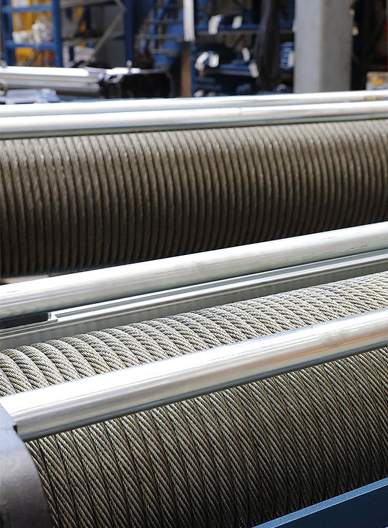
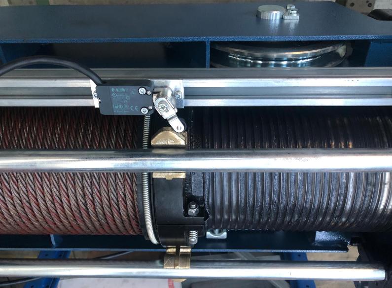
- Incorrect winding on the drum. This problem can lead to snags and crushing of the ropes. It is recommended to use grooved drums to avoid this problem;
- Incorrect unwinding of the rope. At the time of the installation the ropes must be wound keeping them taut at all times to avoid twisting and the formation of knots and folds that can alter the balance of the strands. To avoid this problem, the winding operation must be carried out after inserting the coils or the braces on which the ropes are wound in a stand.
- Collision of the rope against obstacles. This type of accident can occur during the lifting and during unwinding operations;
- Exposure to extreme temperatures;
- Exposure to rain, ice or snow;
- Exposure to chemical or corrosive substances or to dust;
- Exposure to electricity. This can occur as a result of direct contact with electrical wires or indirect contact following the formation of arcs;
- Application of unforeseen stresses. This occurs when a load is applied or released unexpectedly. The loading and unloading operations must be performed gradually.
Another reason for extraordinary inspection of the ropes is the frequent lifting of loads with a weight close to the minimum breaking value. This value is reliable only for new ropes while it decreases over time due to use and wear.
When to replace a rope
A loading rope must be replaced when ordinary and extraordinary inspections bring to light the following problems:
- Breakage of the wires. In itself, the breakage of a wire does not compromise the strength and therefore the use of the rope. Indeed, a table supplied with the lifting ropes indicates the number of broken wires that can be tolerated along a given section of the rope. If this value is exceeded, the rope must be replaced immediately;
- Breakage of a strand. The rope must be replaced when the section of even just one strand is reduced by 40%;
- Reduction of the original diameter. When the original diameter of the rope is reduced by 10% even at just one point;
- Protrusion of the core. When the core protrudes from the strands surrounding it or when they are bent or crushed, uncovering it;
- Wear. The flattening of the wires with a reduction in diameter of 50% must be dealt with in the same way as a breakage. In this case, the values indicated in the tables regarding the tolerable number of broken wires apply;
- Deformation of the rope. When the rope is permanently crushed, dented, twisted or bent;
- Deformation of a strand. When one of the strands appears loose or bulging under load conditions.